
Description
Advantages using our Spiral Contractometer
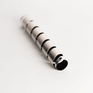
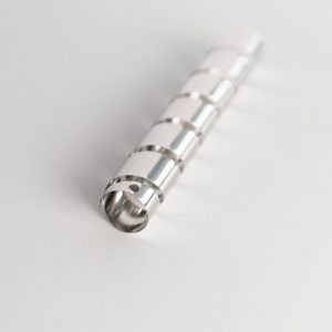
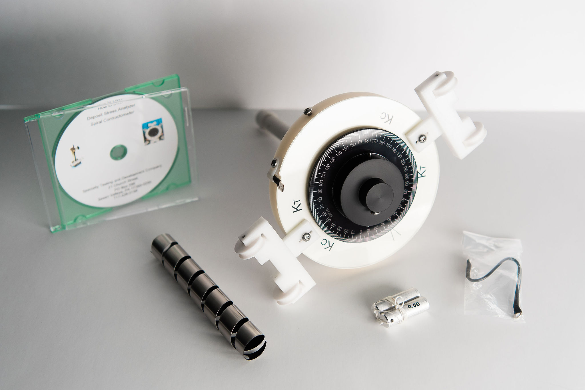
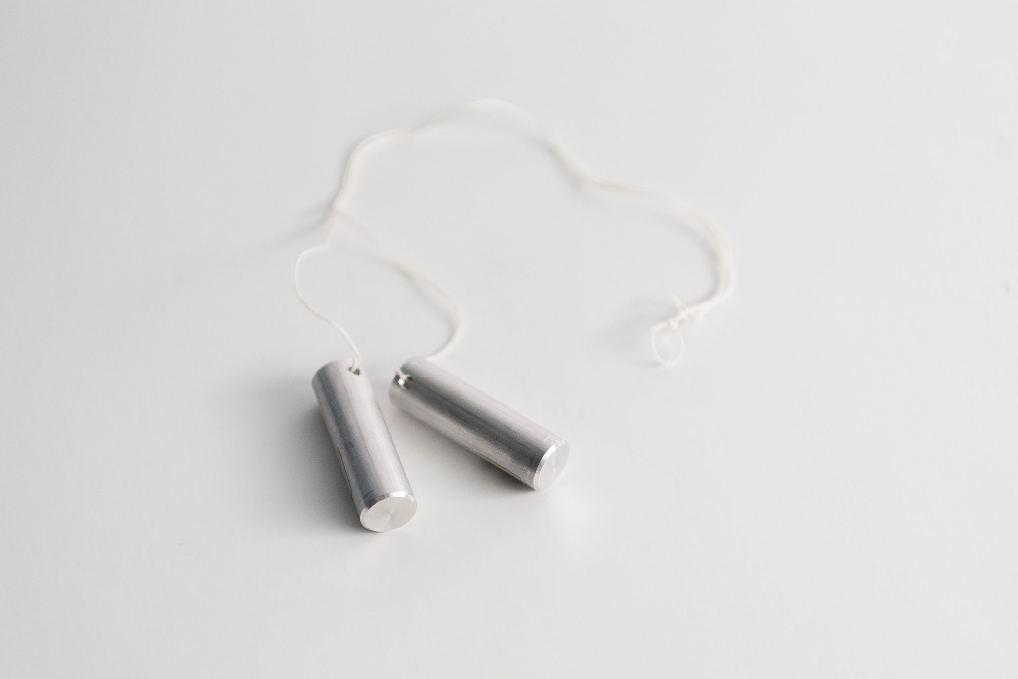
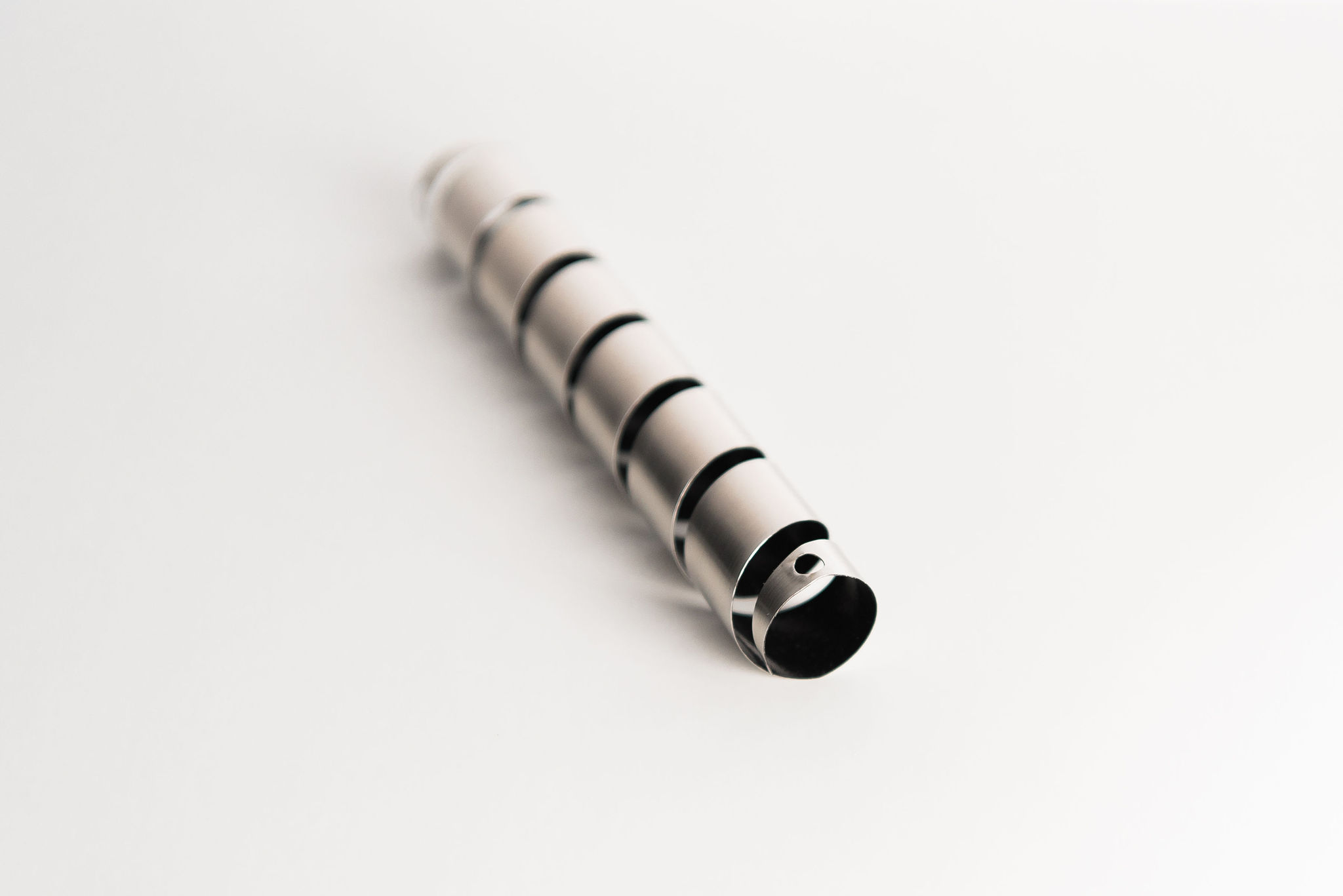
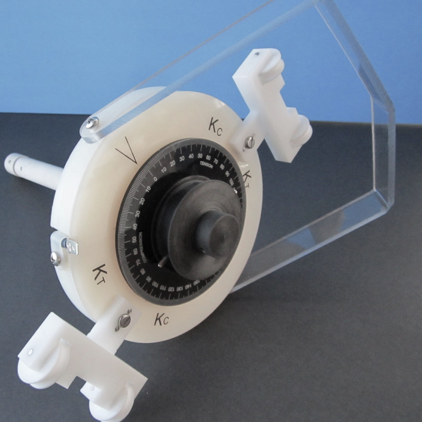
Our design for spiral contractometers corrects problems that are common with earlier models. This design features an interior 3/4th inch diameter shaft over which the spiral (helix) is attached. The shaft serves as a shield to significantly reduce the quantity of the applied deposit on the interior surface of a plated helix. Spirals (Helices) are recommended for use with our design contractometer are fully plated externally tip to tip so the deposit surface area remains the same, avoiding an estimated guess and simplifying the calculations all of which are non-metric. Each spiral (helix) is 0.010 in thick, has a surface area of 13.57 in squared and has a hole near each end through which a screw is used to fasten the Spiral (helix) firmly to the shaft so spiral (helix) slippage during the test period is not possible. Also, stainless steel insert construction prevent contractometer thread damage.
The recommended average test deposit thickness for 0.010 in thick spirals (helices) is 5×10 -4 power in for hard deposits such as nickel. Deposit thickness values as great as 25×10 -4 power may become necessary for soft metallic deposits.
| Advantages | Improvements |
| Accurate repeatable results | Thread stripping is prevented |
| Easy centering of the spiral (helix) | Reduced calibration wheel friction |
| Easy centering of the anode basket | 25% glass filled Fluoropolymer construction |
| Holes at spiral(helix) ends- no slippage | Inside spiral (helix) surface is shielded |
| Simple and rapid calculations | Minimal deposit on spiral (helix) interior |
| Guess steps are eliminated | Precise scale to arrow view |
SPIRAL CONTRACTOR MEASUREMENT METHOD AND CALCULATIONS
1. SPECIALTY TESTING AND DEVELOPMENT COMPANY SPIRALS (Helices)
Specialty Testing and Development Co. spirals (Helices) are constructed from 0.010 inch thick stainless steel and each has a precise surface area of 13.57 square inches. The spiral mounts on the contractometer in a manner that permits plating on the entire outside surface of the spiral and minimizes deposition on the inside of the spiral. Thus, there is no need to estimate the surface area that has been plated. The recommended average test deposit thickness is 500 microinches, (0.000500 inch).
2. PROPERTIES AND TEST CONDITIONS FOR STAINLESS STEEL SPIRALS
SPIRAL (helix) FOR SPECIALTY TESTINGS CONTRACTOMETER
| Surface Area, in² | 13.57 |
| Square Feet | 0.0942 |
| Amps per sq. foot | 30 |
| Amps | 2.90 |
| Stock Thickness, inches | 0.010 |
| Avg. Deposit Thickness, µʺ | 500 |
| Plating Time, Min & Seconds | 20 M & 40 S |
| Plating Solution Temperature | 130º ± 1.5º F |
NOTE: For the purpose of illustration and explanation, electrolytic plating of nickel will be used.
A. Equipment Needed:
- Spiral Contractometer with calibration weights (PN: KSC114)
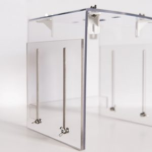
- Spiral Contractometer adjustable Support Stand (PN: SAS141)
- Titanium anode basket 5ʺOD for nickel bath (PN: ABL14)
- 4,000 ml Pyrex beaker for plating bath (other source)
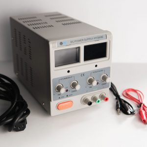
- Direct Current Power Supply 0-6 Amp output constant amp constant voltage (PN: HY3006)
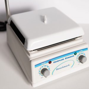
- Magnetic Stirrer Hot Plate (PN: MSH4000)
- Digital Temperature Controller prewired with probe (PN:590TC)
- Spirals (Helices) constructed from 0.010 inch thick stainless steel having an surface area of 13.57 in² (PN: CTS214)
B. Spiral (Helix) preparation and use.
- Place the anode basket containing nickel anode buttons in a 4,000 ml Pyrex beaker, then place the beaker over a magnetic stirrer hot plate, add the desired plating solution to the beaker, then place the spiral contractometer adjustable support stand over the beaker and anode basket and warm the plating solution to the desired temperature.
- If a nickel strike is required for deposit adhesion, pour a nickel strike solution into an approximate 3,000 ml beaker (approx. 9.5″ tall) containing an anode basket with nickel anode buttons along the beaker’s inside parameter.
- Clean a spiral (helix) as the cathode (positive charge) in an alkaline steel electrocleaner at 3 amps for 30 seconds and water rinse. If spiral (helix) is clean skip #4.
- Immerse the spiral (helix) in 20% hydrochloric acid solution for 30 seconds, then water rinse.
- If a Nickel strike is necessary for adhesion of the deposit Nickel strike the spiral (helix) at 3 amps for 1 minute. Remove the spiral (helix) from the spiral contractometer, water rinse, acetone rinse and dry.
- Weigh the spiral (helix) to the nearest milligram and record its weight. Note: use finger cots to prevent contamination of the spiral (helix).
Deposit weight in grams: __________
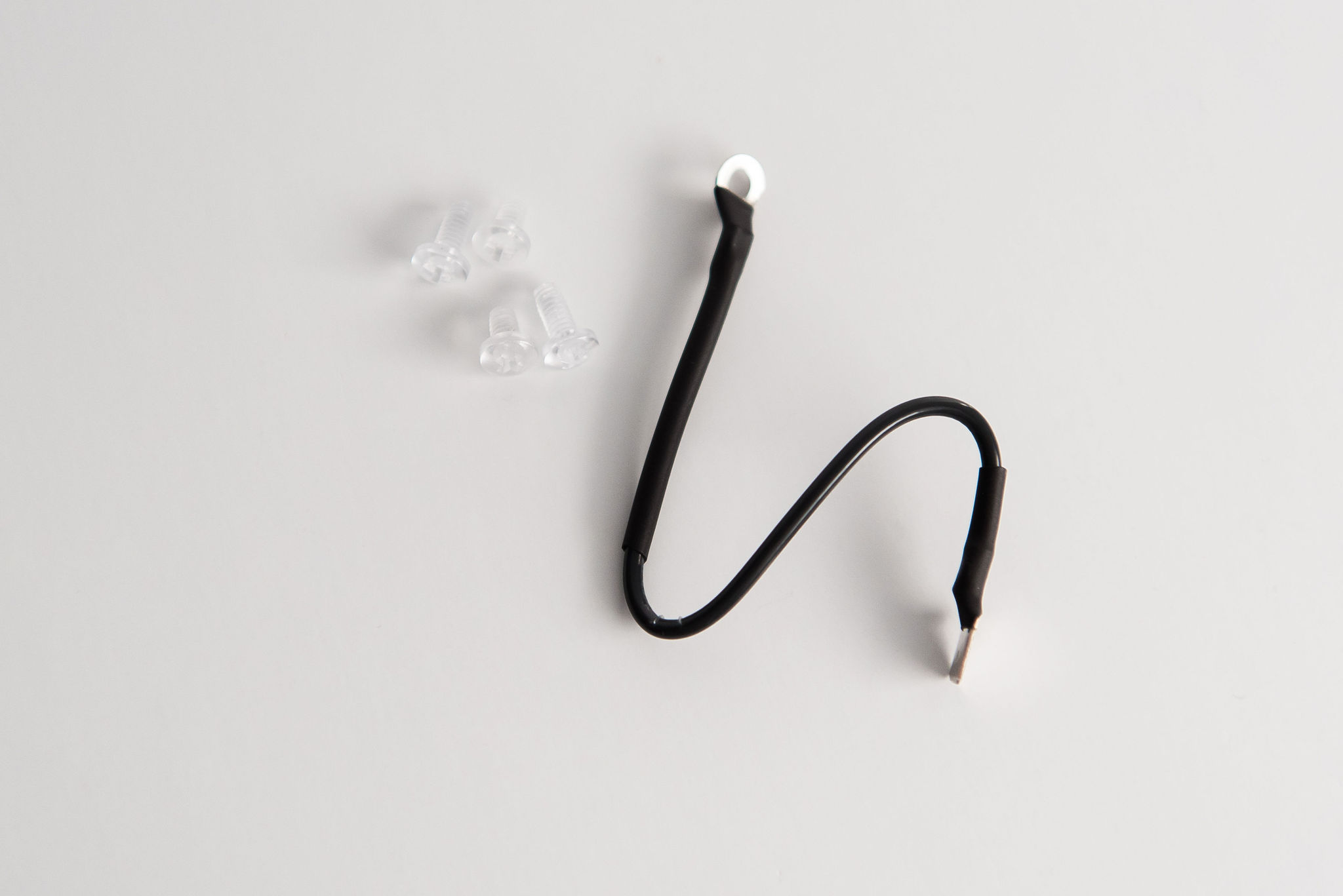
- Mount the spiral (helix) onto the spiral contractometer and tighten the polycarbonate screws through the spiral (helix) holes provided at each end to prevent slippage during the plating process.
- Place the spiral (helix) contractometer assembly on the adjustable support stand and center it by engaging the centering holes in the top surface of the stand.
Note: If the pulley wheel is not freely moving take out the screw at the top of the wheel and remove the rod. Clean the rod to make sure there is nothing that is jamming the movement. If this doesn’t help check the rod to make sure it’s straight. If you have a bent rod contact us for a replacement.
C. Calibration of the spiral (helix).
-
- Loosen the screw that holds the pulley wheel tight against the top of the center rod and position the dial by rotating it to match the zero with the arrow, then tighten the screw to secure the rod so slippage cannot occur.
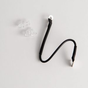
- Put the loop of a calibration thread over a pulley calibration pin and wrap the string around the pulley wheel clockwise, then place the thread and 0.5 ounce weight over the extended grooved wheel near Kc.
- Put the loop of the second calibration thread over the remaining calibration pin near the remaining Kc and hang the weight over the wheel provided. Lightly tap the top of the contractometer pulley to equalize the dial position. Record the Kc degrees. Remove the calibration strings and tap the top of the contractometer, Verify that the dial returns to the zero mark. If not repeat steps 2 and 3.
Kc degrees: Average:
-
- Repeat this process again, this time wrapping the threads in a counterclockwise direction and looping the weights over the wheels near the Kt positions. Record the degrees tensile as Kt. Then remove the calibration strings and weights. Verify that the dial returns to the zero mark. If not repeat steps 2 and 3. Repeat and average the results if desired.
Kt degrees: Average:
D. Plating the Spiral (Helix).
- Plate the spiral (helix) at 2.90 amps for 20 minutes and 48 seconds.As soon as possible after the spiral (helix) has been plated, tap the top of the contractometer lightly, observe and record the degrees deflection at the arrow point and the nature of the stress as tensile or compressive. Compressive stress is indicated by a negative sign.Degrees deflection caused by the deposit:
- With the spiral (helix) on the contractometer, rinse it in water and isopropyl alcohol, then remove the spiral (helix) from the contractometer using finger cots so as to not adversely affect the weight of the spiral (helix) and dry it thoroughly.
E. Calculations.
1. Weigh the dry spiral (helix) and record its weight in grams.
Spiral (Helix) weight in grams:
__________
Subtract from this weight the before plating weight to obtain the weight of metal deposited.
Deposit weight in grams:
___________
2. Calculate the average nickel deposit thickness in inches.
T = W = Inch Where
D (87.53 cm²) (2.54 cm / inch)
W = Grams of nickel deposit,
D = Density of nickel = 8.90 g/cm³ for pure nickel and,
T = Deposit thickness in inches.
For the Specialty Testing spirals plated on the spiral contractometer, the constant spiral (helix) plated surface area is 13.57 in² and the following shortened formula applies:
T = W = Inch
1978.7
For the spirals (helices) attached by circular rings, the surface area plated must be determined by wrapping the spiral (helix) tightly around a 3/4 inch diameter rod. Then the diameter and estimated plated length in inch values are used to calculate the plated surface area as follows:
Surface Area = πdh = inch². This surface area value replaces the 87.53 cm² value in the above equation.
3. Record the average deposit thickness of the spiral (helix) in microinches.
Deposit thickness in microinches: ___________
4. CALCULATE THE DEPOSIT STRESS OF THE APPLIED COATING.
A. Calculate the Deposit Stress in PSI.
Stress = 13.02 (D) X 1 + EDeposit(d) = PSI where
(w) (d) ESubstrate(t)
D = deflection of the spiral (helix) caused by the deposit in degrees,
W = deflection of spiral (helix) on calibration in degrees,
d = deposit thickness in inches,
t = substrate thickness in inches,
EDeposit = Modulus of elasticity nickel = 30,000,050 PSI, and
ESubstrate = Modulus of elasticity of the helix substrate= 28,600,000 PSI
Record the Internal Deposit Stress as PSI:
5. STRIPPING OF SPIRALS (HELICES) FOR REUSE.
- A. Plated spirals (helices) can be stripped of nickel deposits repeatedly in a 50% by volume nitric acid solution for reuse. Do not heat the solution above 90 degrees F. The Fluoropolymer coating remains in place.